- You are here:
-
Home

- Electronics
- Details
- Elektronik
- Hits: 13411
Kommunikation über I2C mit MCP32017
So schön die Prozessorfamilie von ST rund um die STM3-Bit Prozessorfamile auch ist, es gibt ein paar Dinge die sind wirklich schrecklich. Eins davon ist die I2C-Kommunikation. Sofern man nicht ganz(!) genau die diversen States und Flags beachtet geht eigentlich garnichts - nicht mal im Ansatz.
Hintergrund: Als Grundlage für meine geplante Alarmanlage benötige ich noch die Erweiterung von IOs mit sogenannten Port-Extendern.
An anderer Stelle habe ich geschrieben wie man die I2C-Kommunikation mit dem Beagle-Bone oder dem Raspberry Pi hinbekommt. Hier folgen jetzt die Beispiele für den STM32F103x Prozessor.
MCP23017 is ein Portextender von Microchip der meiner Meinung einige ganz gute Eigenschaften hat. Eine davon ist die Möglichkeit einen Interruptausgang anzusteuern wenn sich Port-Bits ändern. So muss man nicht ständig den Zustand pollen. Aber dazu später mehr.
Wie funktioniert die I2C Kommunikation ? Die Grundlagen findet man bei Wikipedia ausreichend, das muss man nicht näher erklären. Aber wie geht das mit einem echten I2C-Busteilnehmer ?
Anschluss des Microchip Expander MCP23017 an den STM32F103RB

Im obigen Schaltbild sind die I2C-Leitungen SCL und SDA direkt mit den passenden Eingängen des Portexpander verbunden. Die STM32-Chips besitzen interne Pullup-Widerstände, sodass die externen I2C-Widerstände (2*3.3k) entfallen können. Der STM32 agiert in den Beispielen als I2C-Master.
Die LEDs und die Taster sind nur zu Test- und Demozwecken vorgesehen. Ich habe den I2C2-Port verwendet, da ich den UART2 bereits verwendet habe und daher der I2C1 nicht gleichzeitig benutzt werden kann.
I2C-Kommunikation benötigt im Prinzip nur die Funktionen I2C-Write und I2C-Read, größere Datenmengen könnte man auch per DMA transferieren.
Hier ist jetzt die grundsätzliche Ansprache des MC23017 zum setzen von Registern:
1. Initialisierung des I2C2-Subsystems im STM32
InitI2C2();
2. I2C-Write Sequenz:
a) Sende Startsequenz
I2C_GenerateSTART
b) sende Adressbyte des MCP-Chips mit RW-Flag=Write
I2C_Send7bitAddres
c) sende Registeradresse des MCP23017 welche beschrieben werden soll
I2C_SendData(I2C2, reg);
d) sende Registerwert
I2C_SendData(I2C2, byte);
e) Sende I2C-Stopsequenz
I2C_GenerateSTOP
Nachfolgend sieht man wie dies im Logikdiagramm aussieht das Register (OLATA=14) wird mit dem Wert 0xFF beschrieben (alle Signale von PortA sind Ausgänge):

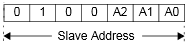
Man muss darauf achten, dass man auch ein Acknowledge-Signal vom Expanderchip bekommt. Wenn kein Acknowledge-Bit (im Bild das Symbol A) gesetzt wird stimmt die I2C-Adresse nicht. Dies kann durchaus sein, wenn man vergisst, dass die I2C-Adressen immer 7-Bit-Adressen sind, und diese ein Bit nach links geschoben werden um Platz für das R/W-Flag zu lassen. Die Basisadresse des MCP23017 ist 0x20, d.h. wenn alle Addressbits A0..A2 auf 0 gesetzt werden, analog zu folgendem Adressschema.
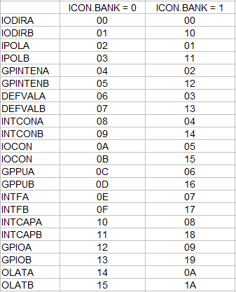
Folgende MCP23017-Register sind zu programmieren
Port-A als Ausgang:
IODIRA = 0x00 : Port A alles auf Ausgang
OLATA = 0x00 : Alle Ausgänge auf 0 entsprechend 0xFF alle Ausgänge auf 1
Port B als Eingang:
IODIRB = 0xFF : Port B alles auf Eingang
GPPUB = 0xFF : Port B enable internal Pullups
Um Taster einzulesen liest man einfach das entsprechende Register des jeweiligen Ports z.B. GPPUB.
1. Initialisierung des I2C2-Subsystems im STM32
InitI2C2();
2. I2C-Write Sequenz:
a) Sende Startsequenz
I2C_GenerateSTART
b) sende Adressbyte des MCP-Chips mit RW-Flag=Write
I2C_Send7bitAddres
c) sende Registeradresse des MCP23017 welche beschrieben werden soll
I2C_SendData(I2C2, reg);
d) sende Registerwert
I2C_GenerateSTART (start repeat)
I2C_Send7bitAddres
c) sende Registeradresse des MCP23017 welche gelesen werden soll
I2C_SendData(I2C2, byte);
I2C_ReceiveData(I2C2);
e) Sende I2C-Stopsequenz
I2C_GenerateSTOP
Um Änderungen abzufragen gibts drei Möglichkeiten:
1. Register GPPUB pollen und damit zyklisch abfragen und vergleichen ob sich was geändert hat.
2. Interrupt Ausgang des MCP23017 so programmieren, dass dieses Ausgangssignal gesetzt wird wenn sich einer der Porteingänge geändert hat. Dieser Interruptausgang kann man dann mit einem Interrupteingang des STM32 verbinden und darauf reagieren.
Nachfolgend ist der Code zum anschauen bzw. zum direkten herunterladen.
 // Wolframs I2C-Lib for STM32 CPUs
#include "stm32f10x_conf.h"
#include "stm32_i2c.h"
void InitI2C2()
{
    /* Initialize I2C on I2C2 port of STM32F103RB Wolframs */
    GPIO_InitTypeDef GPIO_InitStructure;
    I2C_InitTypeDef I2C_InitStructure;
    RCC_APB2PeriphClockCmd(RCC_APB2Periph_GPIOB, ENABLE);
    RCC_APB1PeriphClockCmd(RCC_APB1Periph_I2C2, ENABLE);
    //GPIO_InitStructure.GPIO_Mode = GPIO_Mode_AF;not necessary for I2C2
    GPIO_InitStructure.GPIO_Pin = GPIO_Pin_10 | GPIO_Pin_11;
    GPIO_InitStructure.GPIO_Speed = GPIO_Speed_2MHz;
    GPIO_InitStructure.GPIO_Mode = GPIO_Mode_AF_OD;
    GPIO_Init(GPIOB, &GPIO_InitStructure);
    RCC_APB1PeriphResetCmd(RCC_APB1Periph_I2C2, ENABLE);
    I2C_DeInit(I2C2);
    I2C_InitStructure.I2C_Mode = I2C_Mode_I2C;
    I2C_InitStructure.I2C_OwnAddress1 = 0x12;                                   //own address only in slave mode
    I2C_InitStructure.I2C_DutyCycle = I2C_DutyCycle_2;
    I2C_InitStructure.I2C_Ack = I2C_Ack_Disable;
    //I2C_InitStructure.I2C_Ack = I2C_Ack_Enable;
    //
    I2C_InitStructure.I2C_AcknowledgedAddress = I2C_AcknowledgedAddress_7bit;   //Adress mode 7 bits
    I2C_InitStructure.I2C_ClockSpeed = 100000;                                  //clock rate scl 50kHz
    I2C_ITConfig(I2C2, I2C_IT_ERR, ENABLE);
    I2C_Init(I2C2, &I2C_InitStructure);
    // enable the various interrupt events
    NVIC_InitTypeDef NVIC_InitStructure;
    // Configure the I2C Interrupts for Errors on I2C Bus
    NVIC_InitStructure.NVIC_IRQChannel                   = I2C2_ER_IRQn;
    NVIC_InitStructure.NVIC_IRQChannelPreemptionPriority = 1;
    NVIC_InitStructure.NVIC_IRQChannelSubPriority        = 0;
    NVIC_InitStructure.NVIC_IRQChannelCmd                = ENABLE;
    NVIC_Init(&NVIC_InitStructure);
    I2C_ITConfig(I2C2, I2C_IT_ERR, ENABLE);             // Enable the interrupt in I2C Subsystem

    I2C_ITConfig(I2C2, I2C_IT_EVT, ENABLE);
    I2C_ITConfig(I2C2, I2C_IT_BUF, ENABLE);

    I2C_Cmd(I2C2, ENABLE);                              // finally enable the I2C Port
    I2C_StretchClockCmd(I2C2, ENABLE);
}

void InitI2C1()
{
    /* Initialize I2C on I2C1 port of STM32F103RB Wolframs */
    GPIO_InitTypeDef GPIO_InitStructure;
    I2C_InitTypeDef I2C_InitStructure;
    RCC_APB2PeriphClockCmd(RCC_APB2Periph_GPIOB, ENABLE);
    RCC_APB1PeriphClockCmd(RCC_APB1Periph_I2C1, ENABLE);
    GPIO_InitStructure.GPIO_Pin = GPIO_Pin_6 | GPIO_Pin_7;
    GPIO_InitStructure.GPIO_Speed = GPIO_Speed_2MHz;
    GPIO_InitStructure.GPIO_Mode = GPIO_Mode_AF_OD;
    GPIO_Init(GPIOB, &GPIO_InitStructure);
    RCC_APB1PeriphResetCmd(RCC_APB1Periph_I2C1, ENABLE);
    I2C_DeInit(I2C1);
    // define i2c settings
    I2C_InitStructure.I2C_Mode = I2C_Mode_I2C;
    I2C_InitStructure.I2C_OwnAddress1 = 0x12;        //own address
    I2C_InitStructure.I2C_DutyCycle = I2C_DutyCycle_2;
    //I2C_InitStructure.I2C_Ack = I2C_Ack_Disable;
    I2C_InitStructure.I2C_Ack = I2C_Ack_Enable;
    I2C_InitStructure.I2C_AcknowledgedAddress = I2C_AcknowledgedAddress_7bit;   //Adress mode 7 bits
    I2C_InitStructure.I2C_ClockSpeed = 30000;        //clock rate
    I2C_Init(I2C1, &I2C_InitStructure);
    I2C_Cmd(I2C1, ENABLE);
}

//
// Wolframs read_i2c routine
//
uint8_t read_i2c(uint8_t i2c_address,uint8_t reg){
    uint8_t rec_byte;
    // shift address one bit left (7 bit addressing plus rw-flag)
    I2C_GenerateSTART (I2C2,ENABLE);
    while(!I2C_CheckEvent  (I2C2, I2C_EVENT_MASTER_MODE_SELECT));
    I2C_Send7bitAddress(I2C2, i2c_address << 1, I2C_Direction_Transmitter);
    while(!I2C_CheckEvent  (I2C2, I2C_EVENT_MASTER_TRANSMITTER_MODE_SELECTED));
    I2C_SendData(I2C2, reg);
    while(!I2C_GetFlagStatus(I2C2,I2C_FLAG_BTF));
    I2C_GenerateSTART (I2C2,ENABLE);                    // Start repeat within active I2C communication
    while(!I2C_GetFlagStatus(I2C2, I2C_FLAG_SB));
    I2C_Send7bitAddress(I2C2, i2c_address << 1, I2C_Direction_Receiver);
    while(!I2C_CheckEvent  (I2C2, I2C_EVENT_MASTER_RECEIVER_MODE_SELECTED));
    //I2C_AcknowledgeConfig(I2C2, DISABLE);
    while (!I2C_CheckEvent  (I2C2, I2C_EVENT_MASTER_BYTE_RECEIVED));
    rec_byte = I2C_ReceiveData(I2C2);
    I2C_GenerateSTOP(I2C2, ENABLE);
    return rec_byte;
}
// Wolframs write I2C
void write_i2c(uint8_t i2c_address,uint8_t reg,uint8_t byte){
    I2C_GenerateSTART (I2C2,ENABLE);
    while(!I2C_GetFlagStatus(I2C2, I2C_FLAG_SB));
    // shift address one bit left (7 bit addressing plus rw flag)
    I2C_Send7bitAddress(I2C2, i2c_address<< 1, I2C_Direction_Transmitter);
    while(!I2C_CheckEvent(I2C2, I2C_EVENT_MASTER_TRANSMITTER_MODE_SELECTED));
    I2C_SendData(I2C2, reg);                    // address target register
    while(!I2C_GetFlagStatus(I2C2,I2C_FLAG_TXE));
    I2C_SendData(I2C2, byte);                   // write byte value into the addressed register
    while(!I2C_GetFlagStatus(I2C2,I2C_FLAG_TXE));
    I2C_GenerateSTOP(I2C2, ENABLE);             // stop I2C transission and release bus
    while(!I2C_GetFlagStatus(I2C2, I2C_FLAG_BTF));
}
Und hier noch das Beispielprogramm:
#include "stm32f10x_conf.h"         // STM32 includes
#include "stm32_i2c.h"              // Wolframs i2c Lib for STM32 CPUs
#include "mcp23017.h"               // Wolfram MCP23017 Constants
#include "stdio.h"
#include "core_cm3.h"

/*
#include "stm32f10x_gpio.h"
#include "stm32f10x_usart.h"
#include "stm32f10x_i2c.h"
*/


/* Test program to communicate from STM32F103RB via I2C with MCP 23017 E/SP Port expander
 * Following connections to the MCP chip are necessary
 * The STM32 chip I2C interface 2 is used to avoid conflicts with CAN or UART IOs
 * Connections
 * MCP                              STM32
 * Pin 1..8 and Pin 21..28 GPIOs
 * Pin 9    +Ub
 * Pin 10   GND
 * Pin 12   SCL                     PB10 D29 Pin5 on Ext green
 * Pin 13   SDA                     PB11 D30 Pin6 on Ext orange
 * Pin 18   Reset   +Ub
 * Pin 15   A0  GND
 * Pin 16   A1  GND
 * Pin 17   A2  +UB
 * Address set to 24h (value is 2x )
 * Program PCP to output: set DDRA 00 FF
 * to set all IOA to outputs
 *
 * (c) Wolfram Koerver 5.7.2015
 *
 */

// Function prototypes
void RCC_Init(void);
void USART2_SendString(char* data);

void delay_us(uint32_t nus);
void delay_ms(uint32_t time_ms);

void Int2Str(char *pStr, unsigned int value, int charCount);
void InitUart2(void);

void Init_Led(void);
void blink_yellow(void);
void blink_green(void);

void init_extint1(void);

int main(void)
{
    uint8_t in;
    char            out_text[50];

    out_text[49] = '\0';            // termination

    SystemInit();
    RCC_Init();
    Init_Led();
    InitUart2();
    InitI2C2();
    blink_yellow();

    //init_extint1();                   // in case you want to use the interrupt outputs of MCP

    while(USART_GetFlagStatus(USART2, USART_FLAG_TC) == RESET);
    USART2_SendString("Wolframs Test Program for I2C-Extender MCP23017 \n\r");
    blink_green();
    write_i2c(0x20,IODIRA,0x00);

    write_i2c(0x20,GPINTENB,0xFF);  // enable pin change interrupt on port b

    write_i2c(0x20,IODIRB,0xFF);    // set port b as input
    write_i2c(0x20,GPPUB,0xFF);     // enable pull ups on port b

    in=read_i2c(0x20,MGPIOB);       // read once the input bits


    while(1)
    {
        write_i2c(0x20,OLATA,0x00);                 // Set all PortA Bits to 0
        delay_ms(200);
        write_i2c(0x20,OLATA,0xFF);                 // Set all PortA Bits to 1
        delay_ms(200);
        in=read_i2c(0x20,MGPIOB);                   // Read Input PORT B
        delay_ms(50);
        sprintf(out_text,"In portb: %3d  \r",in);
        USART2_SendString(out_text);
    }
}

void delay_us(uint32_t time_us)
{                                                               // wks version
  SysTick->LOAD  = 8 * time_us-1;
  SysTick->VAL   = 0;                                          /* Loadthe SysTick Counter Value */
  SysTick->CTRL  |= SysTick_CTRL_ENABLE_Msk;                   /* Enable SysTick Timer */

  do
  {
  } while ((SysTick->CTRL & SysTick_CTRL_COUNTFLAG)==0);
  SysTick->CTRL  &= ~SysTick_CTRL_ENABLE_Msk;                  /*Disable SysTick Timer */
  SysTick->VAL   = 0;                                          /* Load the SysTick Counter Value */
}
void delay_ms(uint32_t time_ms) //Delay in msec
{
  while (time_ms>0)
  {
    delay_us(1000);
    time_ms--;
  }
}

void Int2Str(char *pStr, unsigned int value, int charCount)
{
    // this implements sprintf(strVal, "%d", temp); faster
    // note that this is just for values >= 0, while sprintf covers negative values.
    // this also does not check if the pStr pointer points to a valid allocated space.
    // caller should make sure it is allocated.
    // point to the end of the array
    pStr = pStr + (charCount - 1);

    // convert the value to string starting from the ones, then tens, then hundreds etc...
    do
    {
        *pStr-- = (value % 10) + '0';
        value /= 10;
    } while(charCount--);
}


void Init_Led(void)
{
    // the following statements are for the LEDs of the Olimexino STM32 board
    /* Initialize GPIO Structure, configure clock on peripheral bus
     * Enable GPIO Pins for LED which are connected to PA1,5*/
    /* Configure the GPIO_LED pin  PC6 = Green LED PC7 = Yellow LED
     * Configure direction and clock speed*/

    GPIO_InitTypeDef  GPIO_InitStructure;
    RCC_APB2PeriphClockCmd(RCC_APB2Periph_GPIOA, ENABLE);
    GPIO_InitStructure.GPIO_Pin = GPIO_Pin_1|GPIO_Pin_5;
    GPIO_InitStructure.GPIO_Mode = GPIO_Mode_Out_PP;
    GPIO_InitStructure.GPIO_Speed = GPIO_Speed_50MHz;
    GPIO_Init(GPIOA, &GPIO_InitStructure);
}


void blink_yellow()
{
    GPIOA->BRR = GPIO_Pin_1;                     //reset bit
    GPIOA->BSRR = GPIO_Pin_1;                        //set bit
    delay_us(10000);
    GPIOA->BRR = GPIO_Pin_1;                     //reset bit
}

void blink_green()
{
    GPIOA->BRR = GPIO_Pin_5;                     //reset bit
    GPIOA->BSRR = GPIO_Pin_5;                        //set bit
    delay_us(1000);
    GPIOA->BRR = GPIO_Pin_5;                     //reset bit
}
void RCC_Init(void)
{
    // Route and enable clocks for low and high speed bus
    RCC_APB2PeriphClockCmd(RCC_APB2Periph_USART1 | RCC_APB2Periph_GPIOA | RCC_APB2Periph_AFIO | RCC_APB2Periph_GPIOD, ENABLE);
    RCC_APB1PeriphClockCmd(RCC_APB1Periph_USART2, ENABLE);
}


void InitUart2(void)
{

    // Initialize Structs
    GPIO_InitTypeDef GPIO_InitStructure;
    USART_InitTypeDef USART_InitStructure;
    USART_ClockInitTypeDef USART_ClockInitStructure;

    // USART1 RX-Pin initialize PA3
    GPIO_InitStructure.GPIO_Mode = GPIO_Mode_IN_FLOATING;
    GPIO_InitStructure.GPIO_Pin = GPIO_Pin_3;
    GPIO_Init(GPIOA, &GPIO_InitStructure);

    // USART1 TX-Pin initialize PA2
    GPIO_InitStructure.GPIO_Speed = GPIO_Speed_50MHz;
    GPIO_InitStructure.GPIO_Mode = GPIO_Mode_AF_PP;
    GPIO_InitStructure.GPIO_Pin = GPIO_Pin_2;
    GPIO_Init(GPIOA, &GPIO_InitStructure);

    // USART initialize
    USART_ClockStructInit(&USART_ClockInitStructure);
    USART_ClockInit(USART2, &USART_ClockInitStructure);

    USART_InitStructure.USART_BaudRate = 38400;
    USART_InitStructure.USART_WordLength = USART_WordLength_8b;
    USART_InitStructure.USART_Mode = USART_Mode_Rx | USART_Mode_Tx;
    USART_InitStructure.USART_Parity = USART_Parity_No;
    USART_InitStructure.USART_StopBits = USART_StopBits_1;
    USART_InitStructure.USART_HardwareFlowControl = USART_HardwareFlowControl_None;

    USART_Init(USART2, &USART_InitStructure);
    USART_Cmd(USART2, ENABLE);
}


void USART2_SendString(char* data)
{
    while (*data)
    {
        USART_SendData(USART2, (uint16_t) *data);
        while(USART_GetFlagStatus(USART2, USART_FLAG_TC)==RESET);
        data++;
    }
}


void init_extint1(void)
{
    // configure ext interrupt function on pin PB0
    // for MCP23017 interrupt outputs connected to.

    GPIO_InitTypeDef GPIO_InitStructure;
    EXTI_InitTypeDef EXTI_InitStructure;
    NVIC_InitTypeDef NVIC_InitStructure;
    RCC_APB2PeriphClockCmd(RCC_APB2Periph_GPIOB | RCC_APB2Periph_AFIO, ENABLE);
    GPIO_InitStructure.GPIO_Pin = GPIO_Pin_0;
    GPIO_InitStructure.GPIO_Mode = GPIO_Mode_IN_FLOATING;
    GPIO_Init(GPIOA, &GPIO_InitStructure);

    GPIO_EXTILineConfig(GPIO_PortSourceGPIOB, GPIO_PinSource0);

    EXTI_InitStructure.EXTI_Line = EXTI_Line0;
    EXTI_InitStructure.EXTI_Mode = EXTI_Mode_Interrupt;
    //EXTI_InitStructure.EXTI_Trigger = EXTI_Trigger_Rising_Falling;
    //EXTI_InitStructure.EXTI_Trigger = EXTI_Trigger_Rising;
    EXTI_InitStructure.EXTI_Trigger = EXTI_Trigger_Falling;
    EXTI_InitStructure.EXTI_LineCmd = ENABLE;
    EXTI_Init(&EXTI_InitStructure);

    NVIC_PriorityGroupConfig(NVIC_PriorityGroup_4);

    NVIC_InitStructure.NVIC_IRQChannel = EXTI0_IRQn;

    NVIC_InitStructure.NVIC_IRQChannelPreemptionPriority = 0x0F;
    NVIC_InitStructure.NVIC_IRQChannelSubPriority = 0x0F;
    NVIC_InitStructure.NVIC_IRQChannelCmd = ENABLE;
    NVIC_Init(&NVIC_InitStructure);
}

void EXTI0_IRQHandler(void){
    // Interrupt on PB0
    USART2_SendString("Pin Change Interrupt \n\r");
    EXTI_ClearITPendingBit(EXTI_Line0);

}

void i2c_handleErrorInterrupt(void){
  I2C_GenerateSTOP(I2C2, ENABLE);

  I2C_ClearFlag(I2C2, I2C_FLAG_AF);
  I2C_ClearFlag(I2C2, I2C_FLAG_ARLO);
  I2C_ClearFlag(I2C2, I2C_FLAG_BERR);
  USART2_SendString("I2C Error Interrupt Handler \n\r");
}

void I2C2_EV_IRQHandler(void){
    while(USART_GetFlagStatus(USART2, USART_FLAG_TC) == RESET);
    //USART2_SendString("Event Interrupt Handler \n\r");
}

void I2C2_ER_IRQHandler(void){
    I2C_InitTypeDef I2C_InitStructure;
    // This handler is called when there is any error on the I2C Bus; Must be enabled by NVIC
      I2C_GenerateSTOP(I2C2, ENABLE);
    while(USART_GetFlagStatus(USART2, USART_FLAG_TC) == RESET);
    USART2_SendString("ER Interrupt Handler \n\r");

    I2C_ClearFlag(I2C2, I2C_FLAG_BERR);
    I2C_ClearFlag(I2C2, I2C_FLAG_SMBALERT);
    I2C_ClearFlag(I2C2, I2C_FLAG_TIMEOUT);
    I2C_ClearFlag(I2C2, I2C_FLAG_PECERR);
    I2C_ClearFlag(I2C2, I2C_FLAG_OVR);
    I2C_ClearFlag(I2C2, I2C_FLAG_AF);
    delay_ms(500);
    I2C_DeInit(I2C2);
  //NVIC_SystemReset(); // This function works very well in case there is a I2C-Bus error. BUT it does also reset the complete CPU
}
- Details
- Elektronik
- Hits: 7521
Mein neuestes Spielzeug sind die kleinen 15/16Bit ADCs ADS1115 von Texas Instruments. Wunderbare Bausteine die man für wenig Geld an jeder Ecke bekommt. Nachfolgend eine Zusammenfassung wie man diese einfach ansteuert, sowie ein kleines Beispielprogram in C für den STM32.
Im Web finden sich viele der folgenden Platinen, aber obacht - manchmal ist nur ein 12 Bit Chip aufgelötet und man wundert sich warum sich die unteren Bits nie ändern.

Der Chip kann per I2C-Bus angesteuert werden und liefert über 4-Kanäle sogar 15/16bit Auflösung. Ein eingebauter programmierbarer Verstärker ermöglicht Messbereiche von:
0: +-6.144V
1:+-4.096V
2:+-2,048V
3: +-1,024V
4: +-0.512V
5: +-0.256V
Der Baustein kann leider keine negativen Spannungen in Bezug auf GND messen, das geht nur im differentiellen Mode wenn man zwischen zwei Eingängen misst. Daher rührt dan auch die echte Auflösung von 15 Bit im single-ended Mode.
Für die Verwendung mit dem STM32F103 Prozessor habe ich nachfolgend eine kleine I2C- C Library entwickelt. Hier werden die wesentlichen Funktionen des ADS1115 abgebildet. Die Threshold und Interruptfunktion habe ich nicht umgesetzt. Falls ich das irgendwann mal brauche füge ich es noch hinzu.
Im nachfolgenden ZIP-File befinden sich die I2C Lib, die ADS1115 Lib und ein kleines Testprogram. Das Testprogramm kann über ein RS232 Terminalprogramm (115200baud) einfach bedient werden. ? oder --h eintippen und man erhält ein Hilfemenü. Das Testprogramm programmiert den PGA (Programmable Gain Amplifier), sowie den Eingangsbereich und gibt die gemessene Spannung in mV aus.
Hier das Beispielprogram zum Download.
- Details
- Elektronik
- Hits: 35456
Oft muss man Taster oder andere Eingaben in einen Microcontroller einlesen um Aktionen auszulösen. Leider sind Taster "nicht ideale" Schalter, da diese prellen und mitunter erst nach einigen 10ms einen stabilen Logikpegel einnehmen. Man muss Signale also entprellen oder debouncen.
Liest man diese Signale in einen Controller ein, kommt es sicher zu einem Prellen des Signals. Will man eigentlich nur einmal einen Taster betätigen, kann es wahrscheinlich sein, dass mehrere Tastendrücke erkannt werden. Dies ist aber nicht erwünscht. Lösen kann man dies auf zwei Arten. In Hardware durch vorschalten eines Tiefpasses oder Schmitttriggers oder einfacher durch die logische Auswertung der Signale in Software. Dies nennt man auch "debouncen". In Software gibts auch verschiedene Verfahren die alle auch Ihre Nachteile haben. Man könnte z.B. einfach immer ein paar mal den Taster einlesen und bis zu 100ms warten, bevor man den Taster endgültig auswertet. Der Nachteil ist, man muss immer warten ob und wie lange der Taster gedrückt wurde. Warten ist für Controller immer nachteilig, weil der in der Zeit zumeist nicht anderes tun kann.
Hier folgt jetzt ein Programm welches ich von Peter Danneger übernommen habe der diese Debounce Routine für den ATMEGA geschrieben hat. Diese funktioniert wunderbar, ist klein und kompakt. Ich habe diese Routine nur auf den STM32 angepasst.
Wer mehr wissen will kann hier die Details nachlesen.
#include <stdio.h>
#include "stm32f10x_rcc.h"
#include "stm32f10x_gpio.h"
#include <stddef.h>
#include "stm32f10x.h"
#include "stm32f10x_conf.h"
#include <string.h>
#include <misc.h>
#include "stm32f10x_tim.h"
#include "stm32f10x_usart.h"

/*
 * Program to test the TIM2, TIM4 timer and interrupt function for STM32F103RB to read debounced keys press
 * tested with OLIMEXINO STM32 (F103RB)  Board
 * **********************
 * Wolfram Koerver - 2013
 * **********************
 * The Port C is used to read in button pressed events. This uses TIM4 for counting with 10ms.
 * The debounce functions - I have modified to work with STM32 IOs - are invented originally by Peter Danneger
 *
 * Hardware STM32 Olimexino Connections:
 * A0/D15/PC0 == Switch to GND = SW1
 * A1/D16/PC1 == Switch to GND = SW2
 * Serial Port connected to USART2
 * D0 = Input -> STM32 UART
 * D1 = Output from <- STM32 UART
 */

void init_LED(void);
void blink_yellow(void);
void init_timer2(void);
void init_timer4(void);

void delay_us(uint32_t time_us);
void delay_ms(uint32_t time_ms);

void TIM2_IRQHandler(void);
void init_sys_tick(void);

void RCC_Init(void);

void InitUart2(void);
void InitUart3(void);
void USART2_SendString(char* data);

void init_keyport(void);

uint8_t get_key_state(uint8_t key_mask);
uint8_t get_key_rpt(uint8_t key_mask);
uint8_t get_key_short(uint8_t key_mask);

#define uchar unsigned char

uint32_t	ti;

volatile 	uchar 		rfid_bits[54];
volatile 	uchar 		rfid_bytes[9];

char bufferRx[256],receiveRx[256];
uint16_t	RxCounter;


uint8_t usart_receive_array[] = {0xAA, 0xAA, 0xAA};

uint8_t		new_rfid=0; 	//flag to tell there is a new rfid token received

uint16_t	start_bit_count=0,seq_bit_no,b,k,rbit;

uchar			rc5_bit;				// bit value
uint8_t			bit_time_cnts;				// counts number of timer cycles during a bit reception
uint16_t		rc5_tmp;					// shift bits in
uchar			rfid_bit;					// actual received logical bit from RFID stream

volatile uint16_t	rc5_data;				// store result
/********************************** Debounce Variables **********************************/

#define KEY_PIN GPIO_ReadInputData(GPIOC)

#define KEY0            0
#define KEY1            1
#define KEY2            2
#define ALL_KEYS        (1<<KEY0 | 1<<KEY1 | 1<<KEY2)

#define REPEAT_MASK     (1<<KEY0 | 1<<KEY1)       // repeat: key1, key2
#define REPEAT_START    50                        // after 500ms
#define REPEAT_NEXT     10                        // every 200ms

volatile uint8_t key_state;                                // debounced and inverted key state:
                                                  // bit = 1: key pressed
volatile uint8_t key_press;                                // key press detect

volatile uint8_t key_rpt;                                  // key long press and repeat

#define sw1	0
#define sw2	1
#define sw3	2
#define sw4	3
/****************************************************************************************/
int main(void)
{

	extern unsigned char			rc5_bit;				// bit value

	char text[10];
	char			out_text[50];

	out_text[49] = '\0';	// make sure string termination

	text[9]	=0x00;
	uint8_t ky;


	SystemInit();					// initialize the core
	RCC_Init();
	InitUart2();

	/****************************************/
	/* Watchdog Test - Base frequency 40kHz */
	// These calls initiate the watchdog timer interrupts. If watchdog time expires the CPU is reset
	IWDG_WriteAccessCmd(IWDG_WriteAccess_Enable);
	IWDG_SetPrescaler(IWDG_Prescaler_256);
	IWDG_SetReload(3000);	// should be about 1/156s * 3000 should be 20s
	IWDG_ReloadCounter();
	IWDG_Enable();
	/****************************************/

	init_LED();						// Init the LED port IO
	init_timer2();					// configure the Timer2 Interrupt
	init_timer4();
	init_keyport();					// configure the key switch input port
	init_extint();					// configure external interrupt

	while(USART_GetFlagStatus(USART2, USART_FLAG_TC) == RESET);
			USART2_SendString("RFID Test Debounce on STM32\n\r");
	rc5_bit=0;						// init RFID INT

    while(1)
    {
    	blink_yellow();						// let the main program do something

		if( get_key_short( 1<<sw1 )){

			sprintf(out_text,"Key sw1 %3d  \r",ky);
			USART2_SendString(out_text);
		}
		if( get_key_short( 1<<sw2 )){
			sprintf(out_text,"Key sw2 %3d  \r",ky);
			USART2_SendString(out_text);
		}
			delay_ms(25);
			IWDG_ReloadCounter();		// Retrigger Watchdog Counter otherwise CPU would be restartet
    }
}

void init_keyport(void){
	GPIO_InitTypeDef GPIO_InitStructure;
	RCC_APB2PeriphClockCmd(RCC_APB2Periph_GPIOC, ENABLE);
	GPIO_InitStructure.GPIO_Pin = GPIO_Pin_0|GPIO_Pin_1|GPIO_Pin_2|GPIO_Pin_3; 	// enable the firts 4 bits as key switch inputs
	GPIO_InitStructure.GPIO_Speed = GPIO_Speed_50MHz;
	GPIO_InitStructure.GPIO_Mode = GPIO_Mode_IN_FLOATING;						// Pin Floating
	GPIO_InitStructure.GPIO_Mode = GPIO_Mode_IPU;								//Pin Up
	//GPIO_InitStructure.GPIO_Mode = GPIO_Mode_IPD;	//Pin Down
	GPIO_Init(GPIOC, &GPIO_InitStructure);
}


void outuchar(uchar val)
{
	char 	buf[3];
	sprintf(buf,"%02X",val);
	buf[3] = '\0';
	while(USART_GetFlagStatus(USART2, USART_FLAG_TC) == RESET);
				USART2_SendString(buf);
}
void outbits(uchar val)
{
	char 	buf[2];
	sprintf(buf,"%d",val & 0x1);
	buf[2] = '\0';
	while(USART_GetFlagStatus(USART2, USART_FLAG_TC) == RESET);
				USART2_SendString(buf);
}

void RCC_Init(void)
{
	// Route and enable clocks for low and high speed bus
	RCC_APB2PeriphClockCmd(RCC_APB2Periph_USART1 | RCC_APB2Periph_GPIOA | RCC_APB2Periph_AFIO | RCC_APB2Periph_GPIOD, ENABLE);
	RCC_APB1PeriphClockCmd(RCC_APB1Periph_USART2, ENABLE);
}


void TIM2_IRQHandler(void){							// Timer Interrupt handler for TIM2 will be called every 10us
  TIM_ClearITPendingBit(TIM2, TIM_IT_Update);		// Clear interrupt pending bit
  bit_time_cnts++;
}
/**************************************************************************************************************/
///////////////////////////////////////////////////////////////////
//
// check if a key has been pressed. Each pressed key is reported
// only once
//
uint8_t get_key_press( uint8_t key_mask )
{
  key_mask &= key_press;                          // read key(s)
  key_press ^= key_mask;                          // clear key(s)
  return key_mask;
}

///////////////////////////////////////////////////////////////////
//
// check if a key has been pressed long enough such that the
// key repeat functionality kicks in. After a small setup delay
// the key is reported being pressed in subsequent calls
// to this function. This simulates the user repeatedly
// pressing and releasing the key.
//
uint8_t get_key_rpt( uint8_t key_mask )
{
  key_mask &= key_rpt;                            // read key(s)
  key_rpt ^= key_mask;                            // clear key(s)
  return key_mask;
}

///////////////////////////////////////////////////////////////////
//
// check if a key is pressed right now
//
uint8_t get_key_state( uint8_t key_mask )

{
  key_mask &= key_state;
  return key_mask;
}

///////////////////////////////////////////////////////////////////
//
uint8_t get_key_short( uint8_t key_mask )
{
  return get_key_press( ~key_state & key_mask );
}

///////////////////////////////////////////////////////////////////
//
uint8_t get_key_long( uint8_t key_mask )
{
  return get_key_press( get_key_rpt( key_mask ));
}


void USART2_SendString(char* data)
{
	while (*data)
	{
		USART_SendData(USART2, (uint16_t) *data);
		while(USART_GetFlagStatus(USART2, USART_FLAG_TC)==RESET);
		data++;
	}
}

void TIM4_IRQHandler(void){							// Timer Interrupt handler for TIM4 will be called every 10ms
	 static uint8_t ct0, ct1, rpt;					// KEY-PIN will becalled to read in key button pressed events
	  uint8_t i;
  TIM_ClearITPendingBit(TIM4, TIM_IT_Update);		// Clear interrupt pending bit
  i = key_state ^ ~KEY_PIN;                       	// key changed ?
   ct0 = ~( ct0 & i );                             	// reset or count ct0
   ct1 = ct0 ^ (ct1 & i);                          	// reset or count ct1
   i &= ct0 & ct1;                                 	// count until roll over ?
   key_state ^= i;                                 	// then toggle debounced state
   key_press |= key_state & i;                     	// 0->1: key press detect
   if( (key_state & REPEAT_MASK) == 0 )            	// check repeat function
      rpt = REPEAT_START;                          	// start delay
   if( --rpt == 0 ){
     rpt = REPEAT_NEXT;                            	// repeat delay
     key_rpt |= key_state & REPEAT_MASK;
   }
}

void USART2_IRQHandler(void)
{
  uint8_t c;
  if(USART_GetITStatus(USART2, USART_IT_RXNE) != RESET)
  {
    /* Read one byte from the receive data register */
	// This routine jsut reads a byte from serial; only for demonstration purposes
    c = USART_ReceiveData(USART2);
   USART_SendData(USART2, c);				//echo byte back
  }
 }

void InitUart2(void)
{
	// Initialize Structs
	GPIO_InitTypeDef GPIO_InitStructure;
	USART_InitTypeDef USART_InitStructure;
	USART_ClockInitTypeDef USART_ClockInitStructure;

	// USART1 RX-Pin initialize PA3
	GPIO_InitStructure.GPIO_Mode = GPIO_Mode_IN_FLOATING;
	GPIO_InitStructure.GPIO_Pin = GPIO_Pin_3;
	GPIO_Init(GPIOA, &GPIO_InitStructure);

	// USART1 TX-Pin initialize PA2
	GPIO_InitStructure.GPIO_Speed = GPIO_Speed_50MHz;
	GPIO_InitStructure.GPIO_Mode = GPIO_Mode_AF_PP;
	GPIO_InitStructure.GPIO_Pin = GPIO_Pin_2;
	GPIO_Init(GPIOA, &GPIO_InitStructure);

	// USART initialize
	USART_ClockStructInit(&USART_ClockInitStructure);
	USART_ClockInit(USART2, &USART_ClockInitStructure);

	USART_InitStructure.USART_BaudRate = 19200;
	USART_InitStructure.USART_WordLength = USART_WordLength_8b;
	USART_InitStructure.USART_Mode = USART_Mode_Rx | USART_Mode_Tx;
	USART_InitStructure.USART_Parity = USART_Parity_No;
	USART_InitStructure.USART_StopBits = USART_StopBits_1;
	USART_InitStructure.USART_HardwareFlowControl = USART_HardwareFlowControl_None;

	USART_Init(USART2, &USART_InitStructure);
	USART_Cmd(USART2, ENABLE);

	USART_ITConfig(USART2, USART_IT_RXNE, ENABLE);

	  NVIC_InitTypeDef NVIC_InitStructure;
	  /* Enable the USART2 Interrupt for reception of bytes */
	  NVIC_InitStructure.NVIC_IRQChannel = USART2_IRQn;
	  NVIC_InitStructure.NVIC_IRQChannelPreemptionPriority = 0;
	  NVIC_InitStructure.NVIC_IRQChannelSubPriority = 0;
	  NVIC_InitStructure.NVIC_IRQChannelCmd = ENABLE;
	  NVIC_Init(&NVIC_InitStructure);
}

void init_timer2(void)
{
	// SystemCoreClock = 72MHz -> APB1 is maximum 36MHz for TIM2,3,4,5 but will be doubled again to 72MHz when prescaler # 0
	// This example uses TIM2 Timer
	// APB1 clock = SystemCoreClock/2 but s.o.

	TIM_TimeBaseInitTypeDef TIM_TimeBase_InitStructure;
	NVIC_InitTypeDef NVIC_InitStructure;

	RCC_APB1PeriphClockCmd(RCC_APB1Periph_TIM2, ENABLE);
	TIM_TimeBase_InitStructure.TIM_ClockDivision = TIM_CKD_DIV1;
	TIM_TimeBase_InitStructure.TIM_Period 			= 9;		// count up to 999 = 1000
	TIM_TimeBase_InitStructure.TIM_Prescaler		= 71;		//72(MHz) -1 Divided by 72
	TIM_TimeBase_InitStructure.TIM_CounterMode 		= TIM_CounterMode_Up;
	// 9,71 = 10us Cycle Time
	// 999,71 = 1ms
	// 1MHz / 500 = 2000 Hz.
	// SystemCoreClock = 72MHz / 72 => 1 MHz Clock with this clock the timer counts up to 999 = 1000 counts =
	// 1/1000 --> 1000 Hz = 1ms cycle time

	TIM_TimeBaseInit(TIM2, &TIM_TimeBase_InitStructure);
	TIM_ITConfig(TIM2, TIM_IT_Update, ENABLE);
	NVIC_InitStructure.NVIC_IRQChannel = TIM2_IRQn;
	NVIC_InitStructure.NVIC_IRQChannelCmd = ENABLE;
	NVIC_InitStructure.NVIC_IRQChannelPreemptionPriority = 0x0F;
	NVIC_InitStructure.NVIC_IRQChannelSubPriority = 0x0F;
	NVIC_Init(&NVIC_InitStructure);
	TIM_Cmd(TIM2, ENABLE);
}
void init_timer4(void)
{
	// SystemCoreClock = 72MHz -> APB1 is maximum 36MHz for TIM4 but will be doubled again to 72MHz when prescaler # 0
	// This example uses TIM4 Timer
	// APB1 clock = SystemCoreClock/2 but s.o.
	TIM_TimeBaseInitTypeDef TIM_TimeBase_InitStructure;
	NVIC_InitTypeDef NVIC_InitStructure;

	RCC_APB1PeriphClockCmd(RCC_APB1Periph_TIM4, ENABLE);

	TIM_TimeBase_InitStructure.TIM_ClockDivision = TIM_CKD_DIV1;

	TIM_TimeBase_InitStructure.TIM_Period 			= 2499;		// count up to 2500
	TIM_TimeBase_InitStructure.TIM_Prescaler		= 143;		//72(MHz) -1 Divided by 144
	TIM_TimeBase_InitStructure.TIM_CounterMode 		= TIM_CounterMode_Up;
	// 9,71 = 10us Cycle Time
	// 999,71 = 1ms
	//2499/143 = 10ms
	// 1MHz / 500 = 2000 Hz.
	// SystemCoreClock = 72MHz / 72 => 1 MHz Clock with this clock the timer counts up to 999 = 1000 counts =
	// 1/1000 --> 1000 Hz = 1ms cycle time

	TIM_TimeBaseInit(TIM4, &TIM_TimeBase_InitStructure);
	TIM_ITConfig(TIM4, TIM_IT_Update, ENABLE);
	NVIC_InitStructure.NVIC_IRQChannel = TIM4_IRQn;
	NVIC_InitStructure.NVIC_IRQChannelCmd = ENABLE;
	NVIC_InitStructure.NVIC_IRQChannelPreemptionPriority = 0x0F;
	NVIC_InitStructure.NVIC_IRQChannelSubPriority = 0x0F;
	NVIC_Init(&NVIC_InitStructure);
	TIM_Cmd(TIM4, ENABLE);
}
void delay_us(uint32_t nus)
{
 uint32_t temp;
 SysTick->LOAD 	= nus * 11;
 SysTick->VAL 	= 0x00;
 SysTick->CTRL 	= 0x01 ;
 do
 {
  temp=SysTick->CTRL;
 }
 while(temp&0x01&&!(temp&(1<<16)));
 SysTick->CTRL = 0x00;
 SysTick->VAL = 0X00;
}


void delay_ms(uint32_t time_ms) //Delay in msec
{
  while (time_ms>0)
  {
	delay_us(1000);
    time_ms--;
  }
}

void init_LED(void)
{
	/* Initialize GPIO Structure, configure clock on peripheral bus
	 * Enable GPIO Pin for yellow LED which
	   Configure direction and clock speed */
	GPIO_InitTypeDef  GPIO_InitStructure;
	RCC_APB2PeriphClockCmd(RCC_APB2Periph_GPIOA, ENABLE);
	GPIO_InitStructure.GPIO_Pin = GPIO_Pin_1;
	GPIO_InitStructure.GPIO_Mode = GPIO_Mode_Out_PP;
	GPIO_InitStructure.GPIO_Speed = GPIO_Speed_50MHz;
	GPIO_Init(GPIOA, &GPIO_InitStructure);
}
void blink_yellow()
{
	GPIOA->BRR = GPIO_Pin_1;						//reset bit
	GPIOA->BSRR = GPIO_Pin_1;					//set bit
	delay_ms(1);
	GPIOA->BRR = GPIO_Pin_1;						//reset bit
}

void toggle_yellow()
{
	GPIOA->ODR ^= GPIO_Pin_7;						// invert pin
}
Das Beispielprogramm zum Download für den STM32 findet sich hier:
- Details
- Elektronik
- Hits: 11291
STM32 Ein- und Ausgabe von digital Informationen
Hier sind die wesentlichen Informationen zur Ein- und Ausgabe von digitalen Werten beim STM32 Prozessor beschrieben.

Hier am Beispiel des STM32F107VC Prozessors. Die Port-Bits fangen bei Pin_0(!) an. GPIO_Pin_0 ist der Prozessorpin 15.
Bitausgabe
Setzen eines einzelnen Bitregisters direkt: (Pin6) auf Port C:
Bit 6 auf logisch 1 setzen: GPIOC->BSRR = GPIO_Pin_6;
Bit 6 auf logisch 0 setzen: GPIOC->BRR = GPIO_Pin_6;
Bit 6 invertieren: GPIOC->ODR ^= GPIO_Pin_6;
oder alternativ die Orginalfunktionen der STM Lib.
Bit 6 auf logisch 1 setzen: GPIO_SetBits(GPIOC,GPIO_Pin6)
Bit 6 auf logisch 0 setzen: GPIO_ResetBits(GPIOC,GPIO_Pin6)
Bit 6 und Bit 9 auf logisch 0 setzen: GPIO_ResetBits(GPIOC, GPIO_Pin6|GPIO_Pin9)
Die direkten Funktionen sind naturgemäß erheblich schneller. Allerdings müsste sich jemand den erzeugten Assembler Code anschauen ob es wirklich so ist.
Portausgabe
Die IO-Ports des STM32 sind jeweils 16 bit breit. Wenn man also einen ganzen Port beschreiben will muss man auch eine Funktion verwenden die 16 Bit variablen verwendet. Dies ist:
Write complete port : GPIO_Write(GPIOC,val);
wobei val eine 16bit variable uint16_t val
sein muss. Oder wieder einzelne Bits setzen mit folgendem Befehl:
GPIO_Write(GPIOC, GPIO_Pin6 | GPIO_Pin9);
Um den Zustand eines Ausgangsports zurückzulesen (weil man nicht weiß wie er gerade gesezt ist) kann man folgende Funktion verwenden:
uint16_t val;
val = GPIO_ReadOutputData(GPIOC, GPIO_Pin6 | GPIO_Pin9);
Achtung diese Funktion liest nur die (!) Setzregister NICHT den Ausgangszustand.
Biteingabe
Einlesen des kompletten Port C:
port_data = GPIO_ReadInputData(GPIOC);
Achtung: Beim Lesen eines Bits kann es passieren dass anscheinend nichts gelesen wird oder das Bit nicht erkannt wird. Die Ursache liegt in den vielfältigen Programmiermöglichkeiten die der STM32 bietet. Man muss vor der Verwendung definieren welche Art der Input sein soll. Hier die dazu benötigten Flags:
GPIO_InitStructure.GPIO_Mode = GPIO_Mode_IN_FLOATING; // Pin Floating
GPIO_InitStructure.GPIO_Mode = GPIO_Mode_IPU; //Pin with pull up R
GPIO_InitStructure.GPIO_Mode = GPIO_Mode_IPD; //Pin with pull down R
Pin Floating ist z.B. sinnvoll wenn man externe Widerstände in anderen Schaltungsteilen hat.
Nachfolgend noch ein einfaches Demoprogramm.
/* Wolfram Koerver
 * STM32 Example for OLIMEX STM32P107 Test Board
 * Toggle green and yellow LEDs Test Program this is the "hello world for electronics"
 * 1.1.2013
 */

#include "stm32f10x.h"
#include "stm32f10x_gpio.h"
#include "stm32f10x_rcc.h"

void init_GPIO(void);

void delay_nus(uint32_t nus);

int main(void)
{
	init_GPIO();
    while(1)
    {
		/* Toggle LEDs which connected to PC6 and PC7 ; Green/Yellow LEDs from Olimex Board*/
		GPIOC->ODR ^= GPIO_Pin_6;						// invert pin
		delay_nus (100000);								// delay a short time
		GPIOC->ODR ^= GPIO_Pin_7;						// toggle other LED
		delay_nus (100000);
    }
}

void init_GPIO(void)
{
    /* Initialize GPIO Structure, configure clock on peripheral bus
     * Enable GPIO Pins for LED which are connected to PC6,7*/
    /* Configure the GPIO_LED pin  PC6 = Green LED PC7 = Yellow LED
     * Configure direction and clock speed*/

	GPIO_InitTypeDef  GPIO_InitStructure;
    RCC_APB2PeriphClockCmd(RCC_APB2Periph_GPIOC, ENABLE);
    GPIO_InitStructure.GPIO_Pin = GPIO_Pin_6|GPIO_Pin_7|GPIO_Pin_8;
    GPIO_InitStructure.GPIO_Mode = GPIO_Mode_Out_PP;
    GPIO_InitStructure.GPIO_Speed = GPIO_Speed_50MHz;
    GPIO_Init(GPIOC, &GPIO_InitStructure);
}

/***************************************************************************//**
 * @brief     delay in n us
 * @param[in] n:delay value
 * @return    None
*******************************************************************************/
void delay_nus(uint32_t nus)
{
 uint32_t temp;
 SysTick->LOAD = nus * 11;
 SysTick->VAL = 0x00;
 SysTick->CTRL = 0x01 ;
 do
 {
  temp=SysTick->CTRL;

 }while(temp&0x01&&!(temp&(1<<16)));
 SysTick->CTRL = 0x00;
 SysTick->VAL = 0X00;
}
- Details
- Elektronik
- Hits: 22945
Das Olimexino-STM32 Demo Board ist ein sehr preiswertes STM32 Demo-Board für kleine Test- und Bastelanwendungen, aber auch sehr gut um zu lernen wie man denn die STM32 CPUs programmiert. Mit einem Preis von unter 20 Euro kann man dies sicher nicht selbst fertigen.
Hier ist das Board beschrieben. Dort und in vielen Internet-Shops kann man dies sehr preiswert bestellen.
https://www.olimex.com/Products/Duino/STM32/OLIMEXINO-STM32/

Das Bild oben zeigt das Board mit angeschlossenem Programmierstecker, ein RS232/USB-Debug-Board sowie dem angeschlossenen CAN-Bus im unteren Bildbereich. Die Stromversorgung kann über ein einfaches Steckernetzteil von z.B. 12V erfolgen
Ich habe dieses Board als preiswertes Testboard für den CAN-Bus im allgemeinen, aber auch für den Test und als möglicher Ersatz meiner CAN-Jalousie-Controller verwendet.
Wie programmiert man das Board ?
PS: Damit die Timer bzw. delay Funktion richtig funktioniert, muss man darauf achten, dass die Quarzfrequenz richtig eingestellt ist.
Die Frequenz des externen Quarzes im header file stm32f10x.h an folgender Stelle ändern:
#if !defined HSE_VALUE
#ifdef STM32F10X_CL
#define HSE_VALUE ((uint32_t)25000000) /*!< Value of the External oscillator in Hz */
#else
#define HSE_VALUE ((uint32_t)8000000) /*!< Value of the External oscillator in Hz */
#endif /* STM32F10X_CL */
#endif /* HSE_VALUE */
Jetzt folgt nur ein Beispiel wie man den CAN-Bus auf dem Board programmmiert.
/*
 * Wolfram Koerver 2013
 * Demoprogram to test the CAN bus with the OLIMEXINO STM32 board from Olimex.
 * April 2013
 * This program just sends out a few CAN bus telegrams at a CAN bus baud rate of 125kbit/s
 * The sample program is very simple and not optmized in any way.
 */
#include "stm32f10x_gpio.h"
#include "stm32f10x_can.h"
#include "stm32f10x_rcc.h"
void GPIO_Blink(void)
{
    int i;
    /* Initialize LEDs mounted on Olimexino board */
    GPIO_InitTypeDef  GPIO_InitStructure;
    /* Initialize LED which is connected to PC6,9 and enable the clocks*/
    RCC_APB2PeriphClockCmd(RCC_APB2Periph_GPIOA, ENABLE);
    /* Configure the GPIO_LED pin */
    GPIO_InitStructure.GPIO_Pin = GPIO_Pin_1;
    GPIO_InitStructure.GPIO_Mode = GPIO_Mode_Out_PP;
    GPIO_InitStructure.GPIO_Speed = GPIO_Speed_50MHz;
    GPIO_Init(GPIOA, &GPIO_InitStructure);
	/* Toggle LEDs which is connected to PC6*/
	GPIOA->ODR ^= GPIO_Pin_1;
	/* delay */
	for(i=0;i<0x500000;i++);
	/* Toggle LED which is connected to PC9*/
	GPIOA->ODR ^= GPIO_Pin_1;
	/* delay */
	for(i=0;i<0x500000;i++);
}
void CAN_init(){
	// define structures
	GPIO_InitTypeDef GPIO_InitStructure;
	CAN_InitTypeDef CAN_InitStructure;
	RCC_APB1PeriphClockCmd(RCC_APB1Periph_CAN1, ENABLE);
	RCC_APB2PeriphClockCmd(RCC_APB2Periph_GPIOB | RCC_APB2Periph_AFIO, ENABLE);
	// CAN transceiver is connected to Pin 8 and Pin 9
	GPIO_InitStructure.GPIO_Pin = GPIO_Pin_8;
	GPIO_InitStructure.GPIO_Mode = GPIO_Mode_IPU;
	GPIO_InitStructure.GPIO_Speed = GPIO_Speed_50MHz;
	GPIO_Init(GPIOB, &GPIO_InitStructure);
	GPIO_InitStructure.GPIO_Pin = GPIO_Pin_9;
	GPIO_InitStructure.GPIO_Mode = GPIO_Mode_AF_PP;
	GPIO_InitStructure.GPIO_Speed = GPIO_Speed_50MHz;
	GPIO_Init(GPIOB, &GPIO_InitStructure);
	GPIO_PinRemapConfig(GPIO_Remap1_CAN1 , ENABLE);
	// **** set the CAN baud rate to 125kHz
	CAN_InitStructure.CAN_Prescaler = 16;
	CAN_InitStructure.CAN_SJW = CAN_SJW_2tq;
	CAN_InitStructure.CAN_BS1 = CAN_BS1_12tq;
	CAN_InitStructure.CAN_BS2 = CAN_BS2_5tq;
	// ****
	CAN_InitStructure.CAN_Mode = CAN_Mode_Normal;
	CAN_InitStructure.CAN_TTCM = DISABLE;
	CAN_InitStructure.CAN_ABOM = DISABLE;
	CAN_InitStructure.CAN_AWUM = DISABLE;
	CAN_InitStructure.CAN_NART = ENABLE;
	CAN_InitStructure.CAN_RFLM = DISABLE;
	CAN_InitStructure.CAN_TXFP = DISABLE;
	CAN_Init(CAN1, &CAN_InitStructure);
}
int main(void)
{
	SystemInit();
	CAN_init();
	CanTxMsg canMessage;		// Define the CAN telegram
	//canMessage.ExtId = 0;
	canMessage.StdId = 0x22;
	canMessage.RTR = CAN_RTR_DATA;
	canMessage.IDE = CAN_ID_STD;
	canMessage.DLC = 8;
	canMessage.Data[0] = 0;
	canMessage.Data[1] = 10;
	canMessage.Data[2] = 20;
	canMessage.Data[3] = 30;
	canMessage.Data[4] = 40;
	CAN_Transmit(CAN1, &canMessage);
	GPIO_Blink();
	canMessage.Data[0] = 0;
	canMessage.Data[1] = 11;
	canMessage.Data[2] = 21;
	canMessage.Data[3] = 31;
	canMessage.Data[4] = 41;
	CAN_Transmit(CAN1, &canMessage);
	GPIO_Blink();
	canMessage.Data[0] = 0;
	canMessage.Data[1] = 12;
	canMessage.Data[2] = 22;
	canMessage.Data[3] = 32;
	canMessage.Data[4] = 42;
	CAN_Transmit(CAN1, &canMessage);
	GPIO_Blink();
}
Dies ist nur ein Minibeispiel um die CAN-Schnittstelle zu konfigurieren und 3 verschiedene CAN-Telegramme auszusenden. Dies auch nur um die grundsätzliche Funktionsweise des CAN Bus mit dem Beagleboard unter LINUX zu testen.
Und so sieht das (TTL)-CAN-Telegram (das letzte) auf dem Logicanalyser aus

SPI1 Schnittstelle
Um einfache Ausgaben auch auf einem kleinen Display auszugeben kann man die SPI-Schnittstelle verwenden. Diese liegt beim Olimexino hier:
SPI1 Pins sind:
SCK : PA5
MISO : PA6
MOSI : PA7
NSS : PA4
Wie das geht steht hier.
Timer und Interrupts
Hier folgt jetzt ein Beispielprogramm wie man die Timer des STM32 programmiert.
#include <stdio.h>
#include "stm32f10x_rcc.h"
#include "stm32f10x_gpio.h"
#include <stddef.h>
#include "stm32f10x.h"
#include "stm32f10x_conf.h"
#include <string.h>
#include <misc.h>
#include "stm32f10x_tim.h"
/*
 * Program to test the TIM2 timer and interrupt function for STM32F103RB
 * tested with OLIMEXINO STM32 Board
 * Wolfram Koerver - 2013
 *
 * Program starts blinking with approx. 5/sec with the yellow LED on port PA1
 * Interrupt is generated every 1000us to flip a signal at PB6 (D5 output)
 */
void init_LED(void);
void blink_yellow(void);
void init_timer(void);
void init_DO(void);
void toggle_do(void);
void toggle_dot(void);
void delay_us(uint32_t time_us);
void delay_ms(uint32_t time_ms);
void TIM2_IRQHandler(void);
void init_sys_tick(void);
int main(void)
{
	SystemInit();					// initialize the core
	init_LED();						// Init the LED port IO
	init_DO();						// init digital output port for digital output signal
	init_timer();					// configure the Timer Interrupt
    while(1)
    {
    	blink_yellow();				// let the main program do something
    	delay_ms(200);
    }
}
void TIM2_IRQHandler(void){			// Timer Interrupt handler for TIM2 will be called every 1ms
  TIM_ClearITPendingBit(TIM2, TIM_IT_Update);	// Clear interrupt pending bit
  toggle_do();						//generate output bit pulse on output
}
void init_timer(void)
{
	// SystemCoreClock = 72MHz -> APB1 is maximum 36MHz for TIM2,3,4,5 but will be doubled again to 72MHz when prescaler # 0
	// This example uses TIM2 Timer
	// APB1 clock = SystemCoreClock/2 but s.o.
	TIM_TimeBaseInitTypeDef TIM_TimeBase_InitStructure;
	NVIC_InitTypeDef NVIC_InitStructure;
	RCC_APB1PeriphClockCmd(RCC_APB1Periph_TIM2, ENABLE);
	TIM_TimeBase_InitStructure.TIM_ClockDivision = TIM_CKD_DIV1;
	TIM_TimeBase_InitStructure.TIM_Period 			= 999;		// count up to 999 = 1000
	TIM_TimeBase_InitStructure.TIM_Prescaler		= 71;		//72(MHz) -1 Divided by 72
	TIM_TimeBase_InitStructure.TIM_CounterMode 		= TIM_CounterMode_Up;
	//
	// 1MHz / 500 = 2000 Hz.
	// SystemCoreClock = 72MHz / 72 => 1 MHz Clock with this clock the timer counts up to 999 = 1000 counts =
	// 1/1000 --> 1000 Hz = 1ms cycle time
	TIM_TimeBaseInit(TIM2, &TIM_TimeBase_InitStructure);
	TIM_ITConfig(TIM2, TIM_IT_Update, ENABLE);
	NVIC_InitStructure.NVIC_IRQChannel = TIM2_IRQn;
	NVIC_InitStructure.NVIC_IRQChannelCmd = ENABLE;
	NVIC_InitStructure.NVIC_IRQChannelPreemptionPriority = 0x0F;
	NVIC_InitStructure.NVIC_IRQChannelSubPriority = 0x0F;
	NVIC_Init(&NVIC_InitStructure);
	TIM_Cmd(TIM2, ENABLE);
}
void delay_us(uint32_t nus)
{
 uint32_t temp;
 SysTick->LOAD 	= nus * 11;
 SysTick->VAL 	= 0x00;
 SysTick->CTRL 	= 0x01 ;
 do
 {
  temp=SysTick->CTRL;
 }
 while(temp&0x01&&!(temp&(1<<16)));
 SysTick->CTRL = 0x00;
 SysTick->VAL = 0X00;
}
void delay_ms(uint32_t time_ms) //Delay in msec
{
  while (time_ms>0)
  {
	delay_us(1000);
    time_ms--;
  }
}
void init_DO(void)
{
	/*
	 * the following statements are for the DO Output Pins to measure
	 * Clock settings. Initialize GPIO Structure, configure clock on peripheral bus
	 * Enable GPIO Pins
	 * Configure direction and clock speed
	 */
	GPIO_InitTypeDef  GPIO_InitStructure;
	RCC_APB2PeriphClockCmd(RCC_APB2Periph_GPIOB, ENABLE);
	GPIO_InitStructure.GPIO_Pin = GPIO_Pin_6;
	GPIO_InitStructure.GPIO_Mode = GPIO_Mode_Out_PP;
	GPIO_InitStructure.GPIO_Speed = GPIO_Speed_50MHz;
	GPIO_Init(GPIOB, &GPIO_InitStructure);
}
void init_LED(void)
{
	/* Initialize GPIO Structure, configure clock on peripheral bus
	 * Enable GPIO Pin for yellow LED which
	   Configure direction and clock speed */
	GPIO_InitTypeDef  GPIO_InitStructure;
	RCC_APB2PeriphClockCmd(RCC_APB2Periph_GPIOA, ENABLE);
	GPIO_InitStructure.GPIO_Pin = GPIO_Pin_1;
	GPIO_InitStructure.GPIO_Mode = GPIO_Mode_Out_PP;
	GPIO_InitStructure.GPIO_Speed = GPIO_Speed_50MHz;
	GPIO_Init(GPIOA, &GPIO_InitStructure);
}
void blink_yellow()
{
	GPIOA->BRR = GPIO_Pin_1;						//reset bit
	GPIOA->BSRR = GPIO_Pin_1;						//set bit
	delay_ms(1);
	GPIOA->BRR = GPIO_Pin_1;						//reset bit
}
void toggle_yellow()
{
	GPIOA->ODR ^= GPIO_Pin_7;						// invert pin
}
void toggle_do()
{
	GPIOB->ODR ^= GPIO_Pin_6;						// invert pin
}
void toggle_dot()
{
	GPIOB->BSRR = GPIO_Pin_6;						//set bit
	GPIOB->BRR = GPIO_Pin_6;						//reset bit
}
Hier jetzt noch der Downloadlink.